John Nelson did it again and amazed us by recreating AI topographic images with ArcGIS Pro. He showed the process in his latest youtube video. You may ask yourself: Can this be done in QGIS as well?
Short answer: sort of.
The main part of this work is to differentiate between the pseudo-3d-ish look and the actual cartographic mastering.
Prerequisites
You will not need any particular skill and any DEM will fit our work. Yet a DEM is best if it also shows some topography.
I am using the SRTM-downloader from Derek Watkins. You need to register for the earthdata website/service to be able to download SRTM data. This is also the case for the QGIS SRTM downloader plugin. You can get access to earthdata quite easily by registering here: https://www.earthdata.nasa.gov/
Furthermore we will need…. QGIS.
Preprocessing
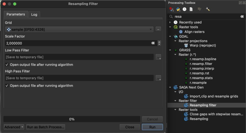
As smaller “DEM islands” are not very handy, we will eliminate topographic outliers prior processing using the SAGA plugin. You can progress without the smoothing but I will follow John’s example here.
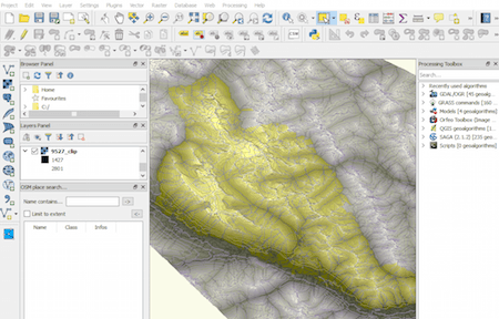
Using the SAGA resampling tool (Processing-> SAGA Next Gen -> Raster Filter -> Resampling Filter) was working very subtle with my DEM using scale factor 2:
Now we will convert the DEM to contours. To work a bit fluently I strongly recommend to only work with parts of the DEM so you will not wait for the calculation of unnecessary data. So: happy clipping!
Lets make it “3D”
Now we need to convert the DEM to a vector dataset using the contour polygons processing in the processing toolbox. For my DEM I will use the 50m interval. Depending on your DEM you might want to change this. The base for the contour lines will be the low pass filter dataset resulting from the above mentioned preprocessing.
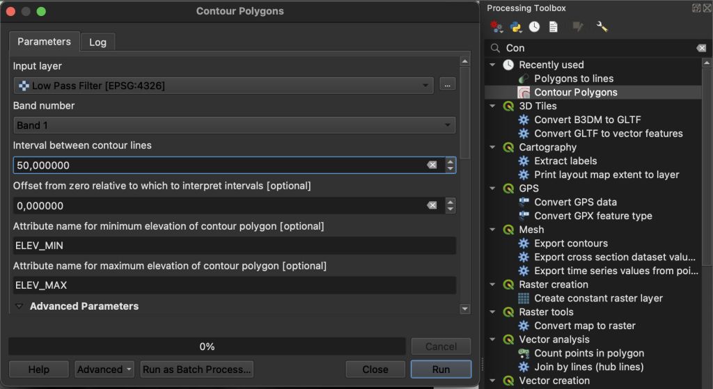
This will group raster cell values in polygons and will assign lower and upper limits as attributes to the dataset.
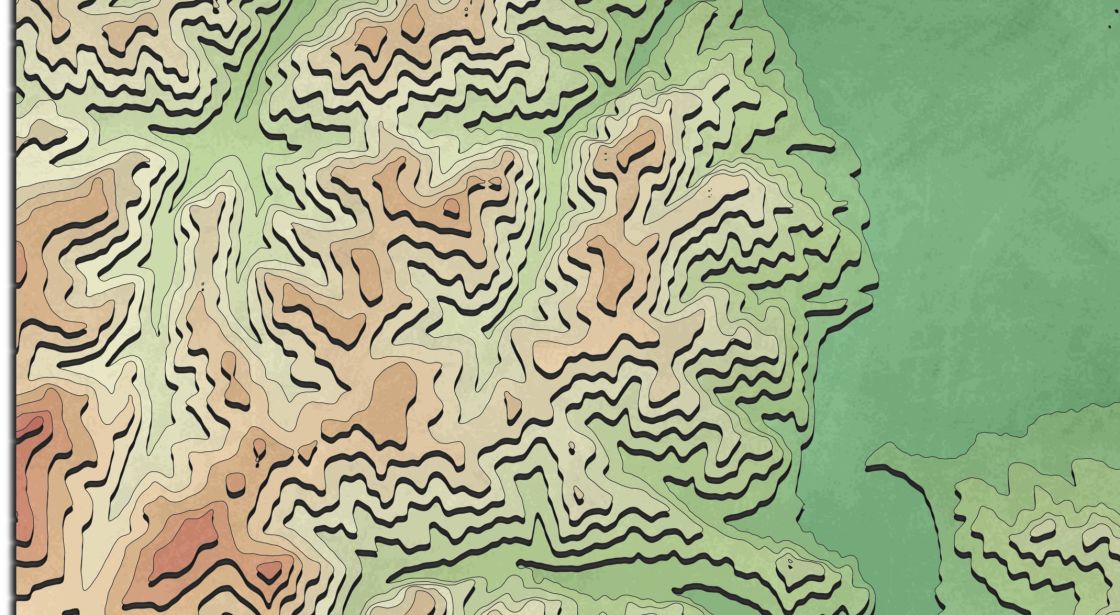
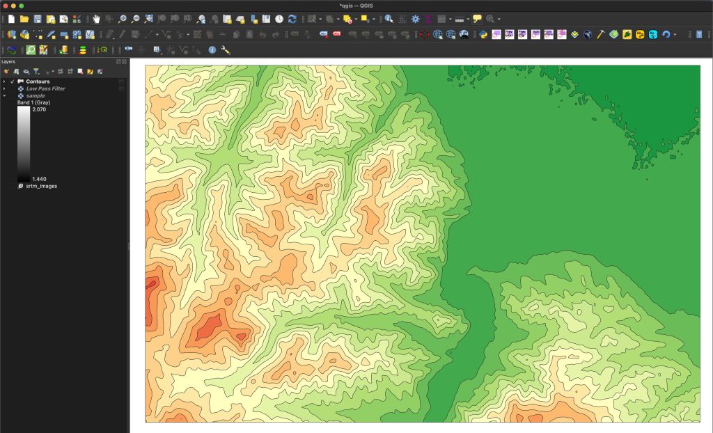
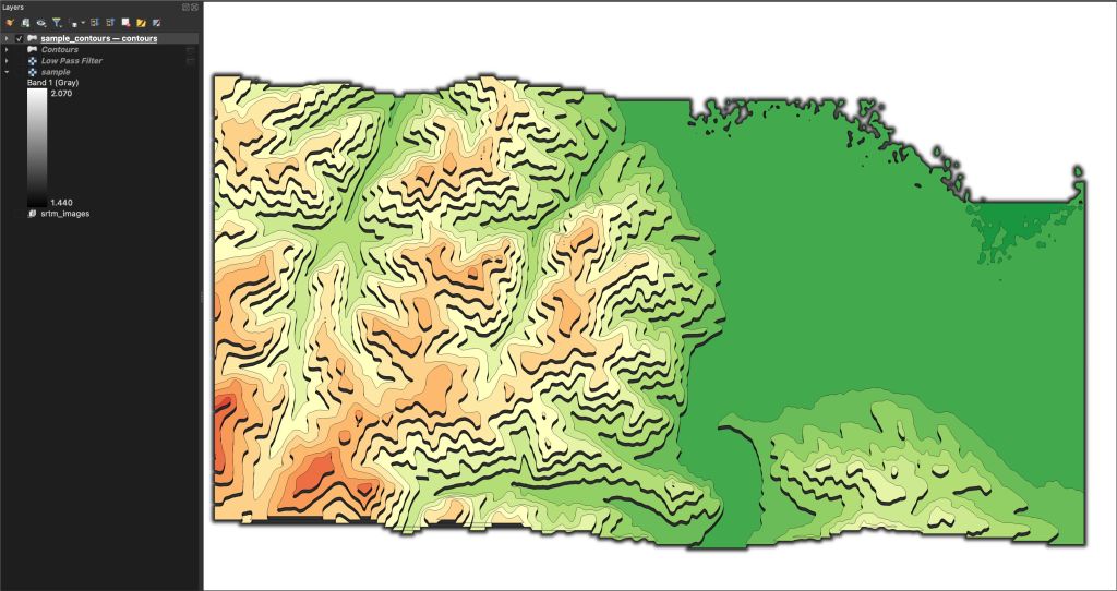
After some styling (categorized style, based on ELEV_MIN values, green-yellow-red color scheme) The result looks as expected:
Now lets add the needed spice.
The main ingredient is the Offset of the used symbol. Go to the layer properties and open the styling section, click on the symbol, select the Simple Fill and Connect the Offset with a variable by selecting a Data defined Override:
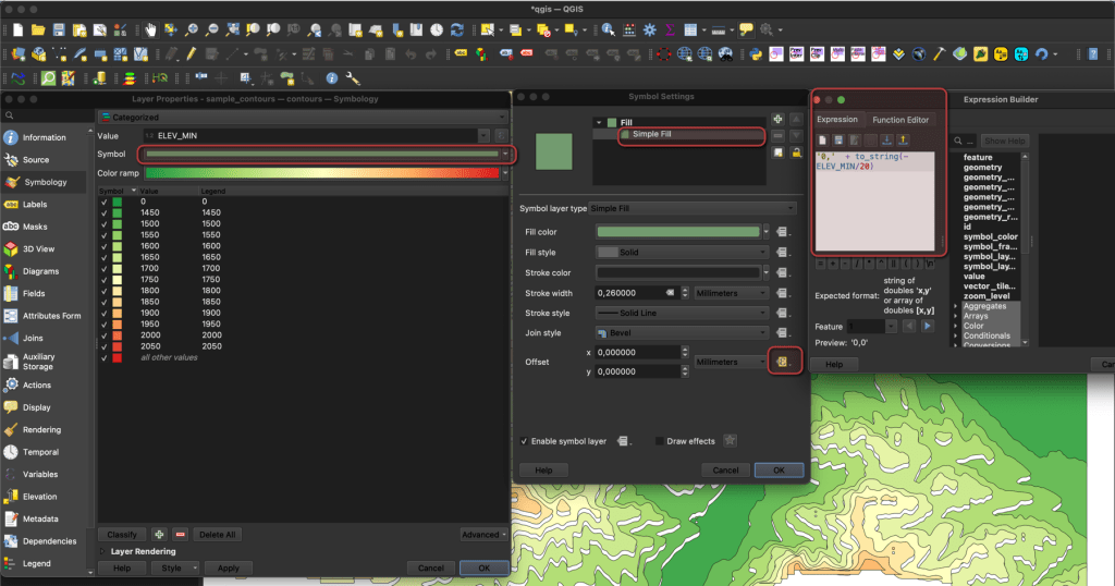
The key formula will look like:
‘0,’ + to_string(-ELEV_MIN/20)
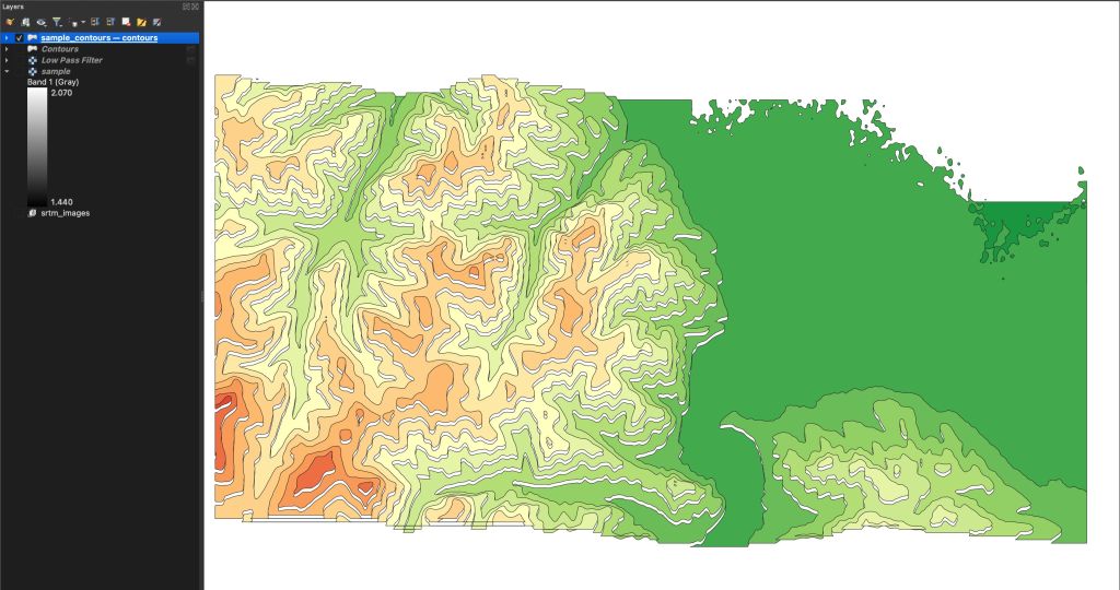
Depending on your data and your desired “look” you will need to adjust the Divisor. I’ve used 20 and higher values will create lower offsets. And you will see a “bug” quite easily. If the original vertex values are outside of the map view, they will not be rendered, even if the offset value would be visible in the map view. The result will always show a white margin at the bottom of the QGIS window:
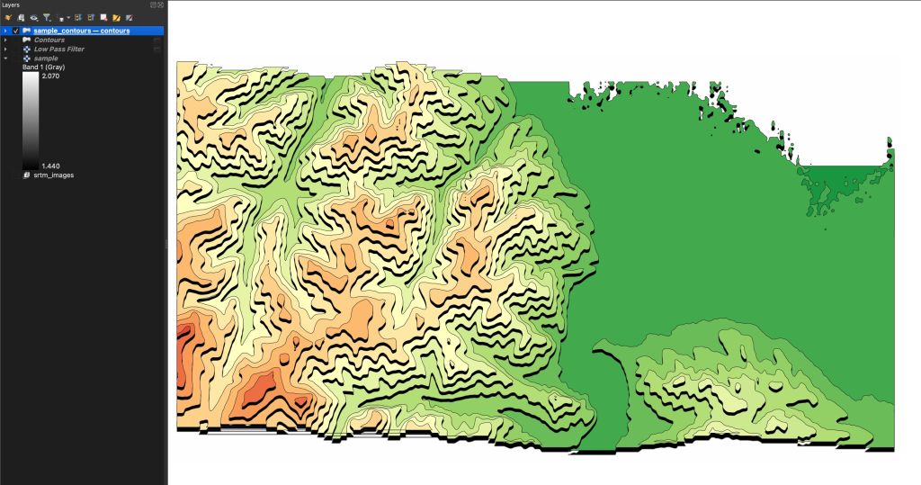
In the end we need to remove the white spaces “below” our offset geometries. Therefore I am using so called “Draw Effects”.
I am using a very shard drop shadow to fill the gaps:

The result is already looking quite good:
You can also go and play around with an outer glow, that might a bit more subtle:

Unfortunately I was not investing more time to recreate John’s results using QGIS but let us add a little different polygon fill to get this “paperboard feeling”.
Finishing
Therefore I am using the chalkboard style from Klas Karlson and it makes it nearly perfect. If you’re unsure, how to apply the style, just follow this tutorial. The result in direct comparison:
What do you think would bring even more of a 3d-ish feeling to such a visualization? Drop me a comment.

Hello Riccardo
Thank you for this amazing tutorial. I followed this tutorial to create this 3dish effect for mount Etna in Italy. The results are amazing. However, with this offset effect, the contours are not appearing at their true place. I used 90 as a divisor. The triangle marker used in this image is the true position of topmost contour and it is shifted after all the effects. can you suggest some solution. I wish to show the contour polygons at true place with this offset effect.
Thank you for your time.
Cheers from India
Neha Joshi
Yes, the offset moves everything… that is the purpose of a offste. You need to offset the markers as well.